Hardware
6-DoF manipulator
A DENSO-class arm carries the roller tool through pick-up, wrapping, offset, and final drag alignment using joint-space trajectories from inverse kinematics.
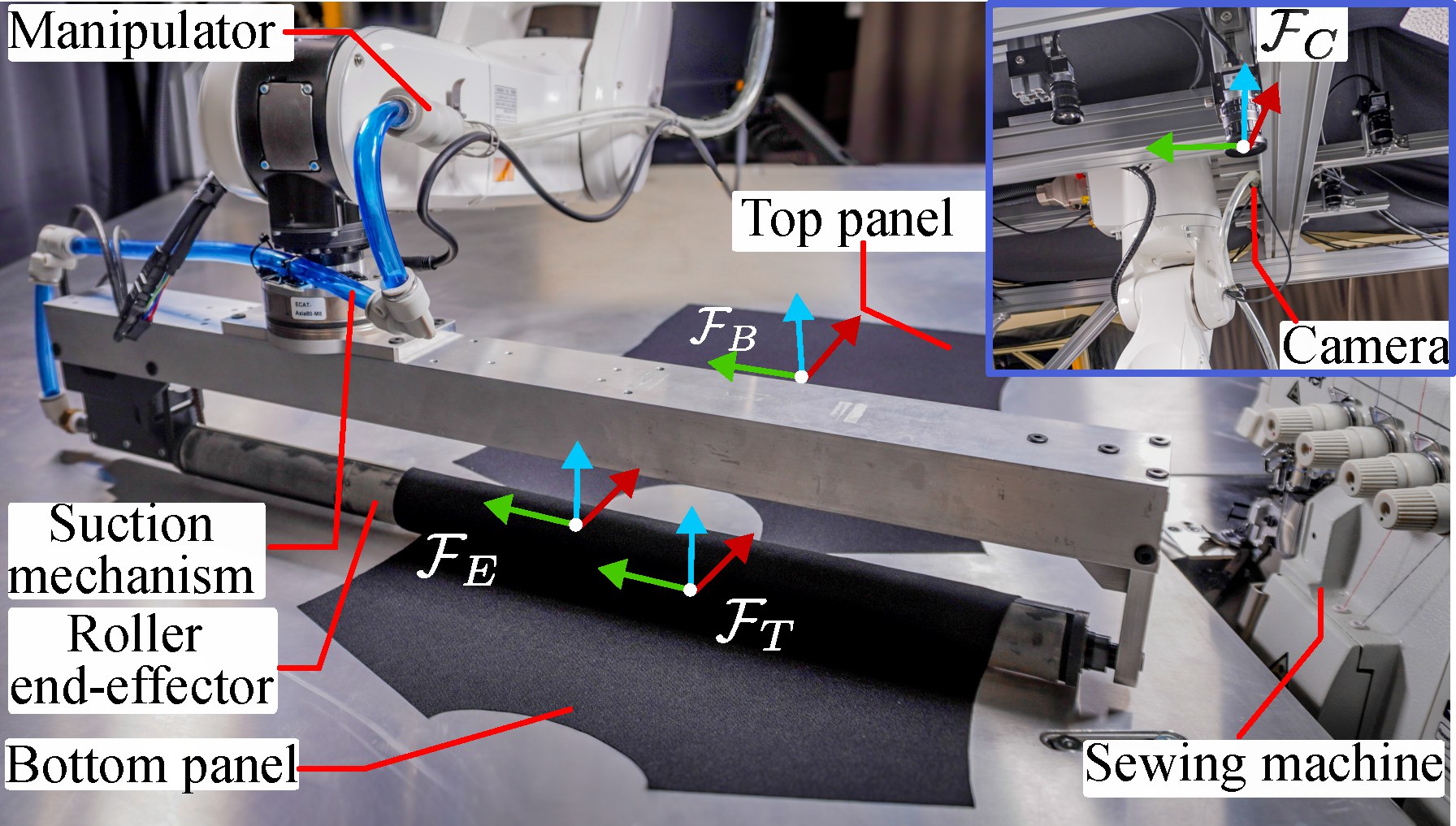
Frames in view: ℱE on the end-effector
GLW-ICP
Millimeter-level edge and sewing-line alignment under occlusion, using Global Local Weighted ICP.
Background
In garment production, sewing is only as good as the placement that precedes it. Aligning a top panel to a bottom panel — edge to edge, seam to seam — still consumes roughly three quarters of sewing operation time, and it is still largely done by hand.
Operators read the cloth the way a tailor does: not only by the cut silhouette, but by the intended sewing line. A millimetre of drift at the seam becomes a crooked collar, a twisted placket, or a garment that never quite hangs right. Vacuum tables and CAD patterns help keep panels flat and consistent, yet cutting error, fraying, shrinkage, and handling deformation still leave the real edge short of the digital ideal.
That is why alignment is hard to automate. Cut edges are noisy global cues. Sewing lines are the true local target — but once a robot grasps the cloth, the camera sees only part of the panel. Standard registration treats every point the same, and collapses under occlusion. The work on this page closes that gap: perceive both global edges and local seams, then manipulate the top panel into place before sewing begins.
The system
Use the tabs to explore each part of the setup. The figure matches the paper’s system overview.
Hardware
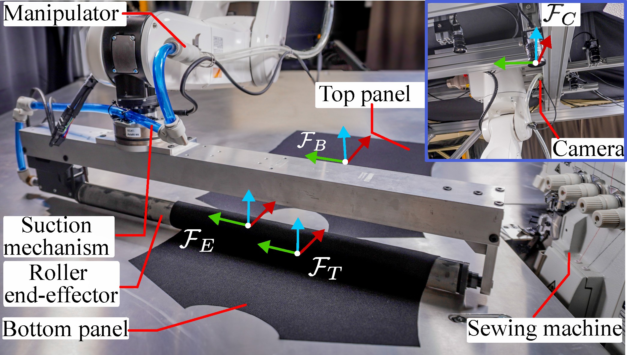
A DENSO-class arm carries the roller tool through pick-up, wrapping, offset, and final drag alignment using joint-space trajectories from inverse kinematics.
Frames in view: ℱE on the end-effector
Fig. 1 — Proposed automatic fabric alignment system. Coordinate frames mark the camera ℱC, end-effector ℱE, top panel ℱB, and bottom/target panel ℱT.
Method
Align CAD edges globally and sewing lines locally. Drop unmatched points in occluded regions with adaptive sparsity. Use the chips under each figure for a short guided reading of the drawing.
What you are looking at. Left: match the observed fabric to a CAD template. Right: use that pose to wrap and drag the top panel into place.
Early iterations. α starts higher so global edge alignment locks the rough pose before trusting fine sewing-line matches.
Higher kratio. More observed points are kept for matching, so the estimate can hug the target contour more tightly when enough of the panel is visible.
Edge and sewing-line correspondences are weighted independently so cutting error does not drag the seam.
Unmatched points under the roller are rejected, keeping pose estimation stable on partially visible panels.
Pose estimates drive a suction roller that wraps, repositions, and releases the top panel for final alignment.
System workflow
Scrub the pipeline. Each step updates the stage and highlight on the workflow diagram.
Step 1 — Initial pose estimation of bottom and top fabrics.
Results
Table I summarized as interactive charts: occluded sewing-line error, success/fail under partial visibility, GLW-ICP vs AW-RICP, and final stacking accuracy — then the qualitative figure that matches those numbers.
Table I · Key results
Under partial visibility, most ICP variants fail. Only AW-RICP and GLW-ICP succeed — and GLW-ICP roughly halves the sewing-line Chamfer error versus AW-RICP.
Soft-capped bars: failures ≫20 mm are marked fail. Hover values in the labels.
GLW-ICP cuts occluded sewing-line error by ~50% vs AW-RICP on every shape.
Mean Chamfer after the full wrap–release–align pipeline. Baselines that fail pose estimation have no final alignment.
Ablation
Single-cue ablations can win one column and still be unusable. Sew-only looks great on sewing metrics, then collapses on global edge pose; Edge-only dies under occlusion. GLW-ICP is the only setting that stays millimetre-level on all three metrics.
Hover bars for exact mean ± std. Soft-scaled axis keeps millimetre wins readable; bars above ~20 mm are marked fail.
Legend. Blue = partially visible fabric. Red dashed = CAD template. Green dots = sewing-line points; red dots = edge points. The task is to lay the template onto the observed cloth despite occlusion.
(a) Initial poses. Both panels lie flat on the table. The camera estimates top and bottom poses with GLW-ICP before any grasp.
Publication
W. Dong, D. Bhattacharya, K. Tang, A. Kobayashi, F. Tokuda, A. Seino, N. C. Tien, and K. Kosuge, “Robotic Fabric Alignment System for Sewing Using Global Local Weighted ICP,” IEEE Trans. Autom. Sci. Eng., vol. 23, pp. 13391–13406, July 2026. doi:10.1109/TASE.2026.3713128
Funded in part by the JC STEM Laboratory of Robotics for Soft Materials, The Hong Kong Jockey Club Charities Trust.
Supplemental video
Clips from the IEEE TASE supplemental video. Jump between chapters, or switch fabric shapes for the real alignment demos (×4 speed).
Complete walkthrough: system overview, pipeline, baselines, and collar / rectangle / shirt alignment.